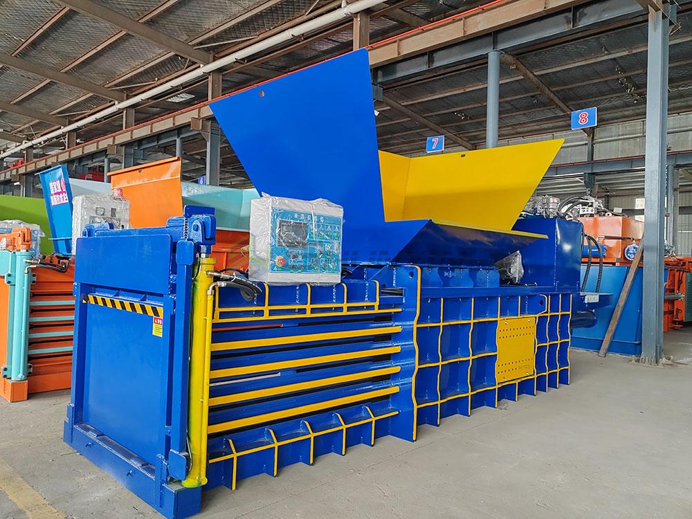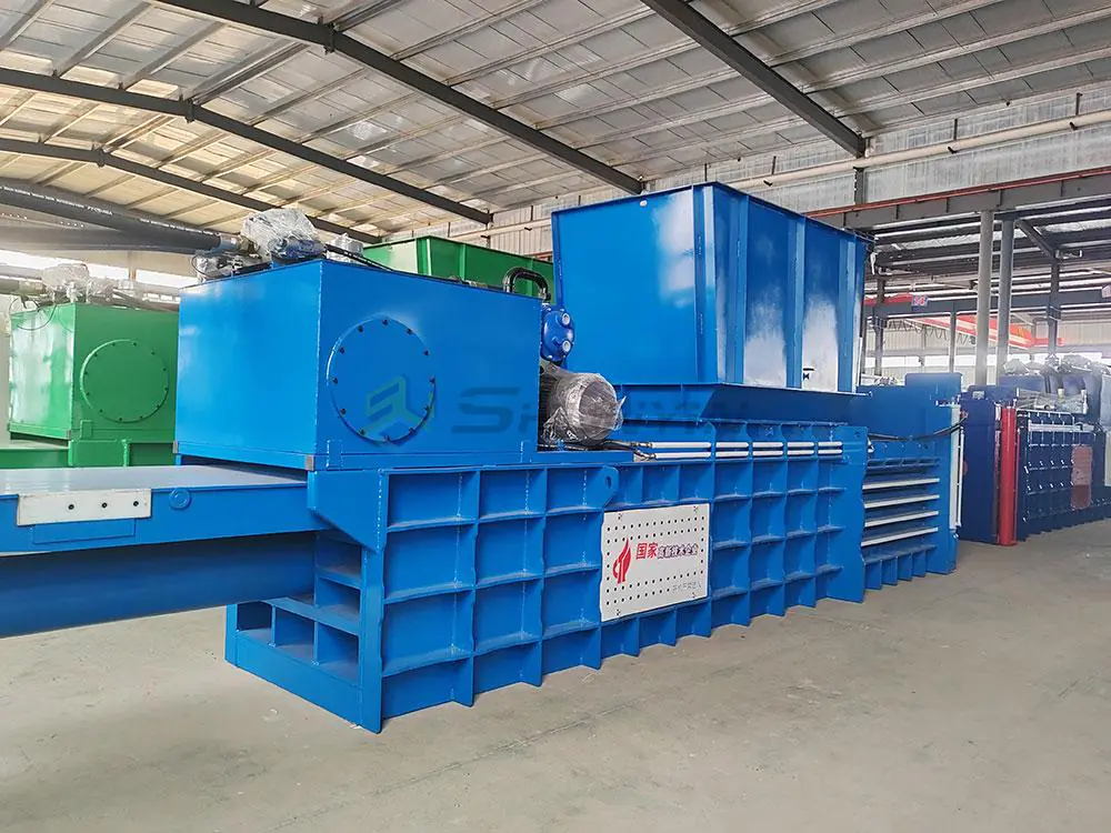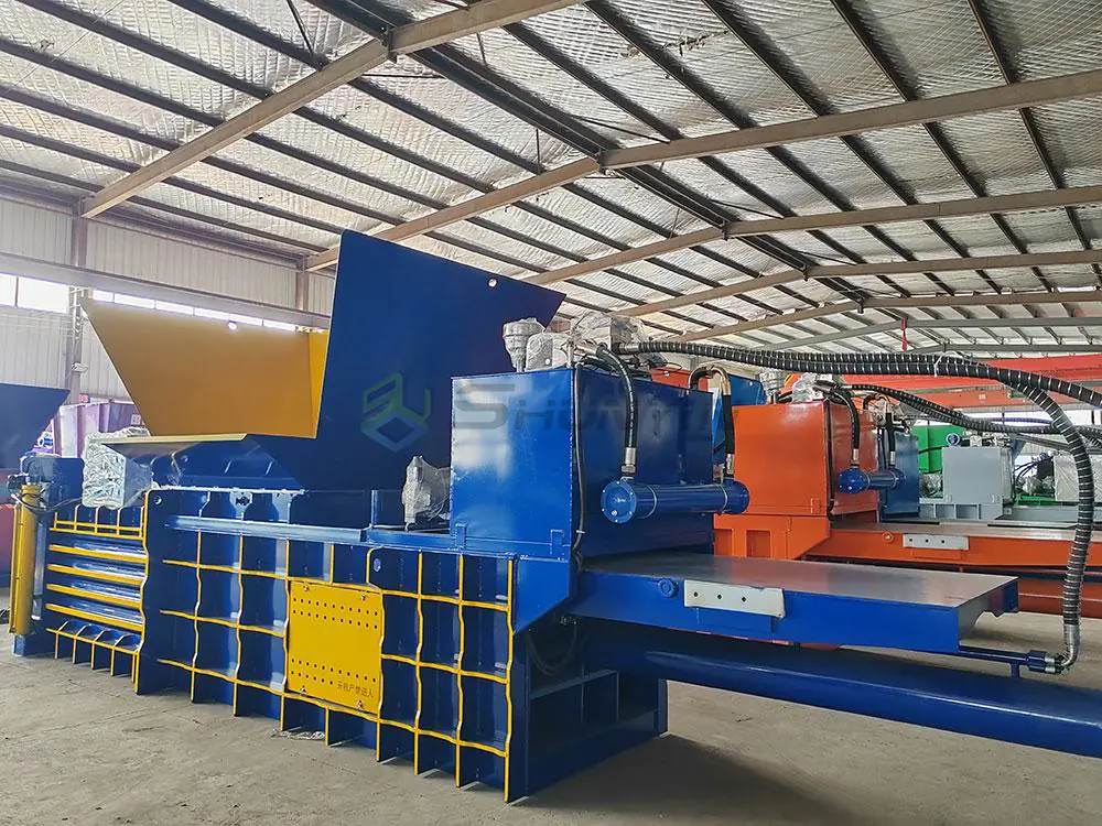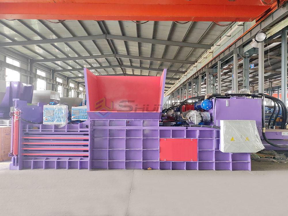

Choosing a horizontal hydraulic baler machine without understanding how it actually works is a common procurement mistake. Buyers compare pressure ratings and motor specs on a datasheet, then discover the machine underperforms on their specific material. That gap between spec sheet and real output is where most purchasing regrets begin — and this article closes it.
A horizontal hydraulic baler works by pushing recyclable material through a multi-stage cycle: loading material into a horizontal feed chamber, compressing it with a hydraulically driven platen, completing multiple compression strokes to build a full bale, tying the bale with wire or strapping, and ejecting it from the discharge end.[^1] Each stage must be matched to your material, volume, and operational requirements to deliver consistent, usable bales.
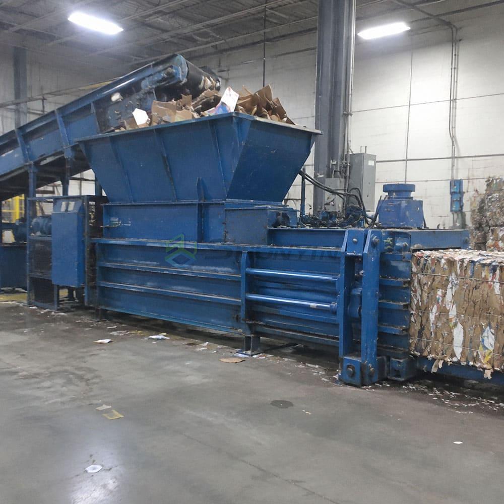
Understanding the cycle in order — from feeding through ejection — helps you evaluate whether a given machine configuration is actually suited to your operation. The sections below walk through each stage, explain what the hydraulic system contributes at each point, and show why material type changes the equation every time.
What Happens During the Feeding Stage of a Horizontal Baler?
Most buyers focus on compression force and overlook the feeding stage entirely. That is a mistake. How material enters the chamber determines how evenly it compresses, how consistent your bale density will be, and how much manual intervention your team will need between cycles.[^2]
The feeding stage sets the entire rhythm of the baler cycle. Irregular feeding — whether from inconsistent material flow, oversized pieces, or wrong feed geometry — introduces variability that downstream compression cannot fully correct, regardless of how powerful the hydraulic system is.
Feed Chamber Design and Orientation
In a horizontal hydraulic baler, the compression axis runs horizontally. Material is loaded from above — through a top-opening hopper or a side-feed conveyor — into a chamber positioned perpendicular to the compression platen's travel direction.
The chamber geometry matters considerably:
- Hopper width and depth determine whether bulky materials like OCC (old corrugated cardboard) or baled film can be loaded without bridging or jamming
- Chamber volume relative to platen stroke affects how many charges are needed per bale
- Feed opening height limits the maximum piece size that can enter without pre-shredding
Manual, Semi-Automatic, and Fully Automatic Feeding
Feeding method varies significantly by machine configuration and operational context:
| Feeding Method | Typical Use Case | Labor Requirement |
|---|---|---|
| Manual top-loading | Low-volume, mixed material streams | Higher — operator-dependent |
| Conveyor-fed semi-auto | Moderate-volume, consistent materials | Moderate — line monitoring |
| Fully automatic shredder-fed | High-volume paper, film, or PET lines | Lower — controlled feed rate |
From what I have observed during machine commissioning, fully automatic feeding produces the most consistent bale weight and density — but only when the upstream material flow is itself consistent. Irregular infeed from a conveyor or manual dumping can still create density variation even on an otherwise automated machine.
How Material Type Affects the Feed Stage
Different materials behave very differently at the feed stage:
- Cardboard and OCC: High bulk volume relative to final bale weight. Requires adequate hopper depth and often benefits from a pre-breaker or press-down roll to manage volume before the platen engages.
- Plastic film (LDPE, stretch wrap): Extremely low bulk density and prone to wrapping around mechanical components. Feed design must manage film tangles.
- PET bottles: Springy and irregular. Loose bottles can bridge across the hopper opening if the feed width is too narrow.
- Textile waste: Dense and interlocked. Can resist compression unless chamber loading is carefully controlled.
Treating these as a single, interchangeable material stream is one of the most common errors I see in early-stage equipment selection.
How Does the Hydraulic Compression System Work?
Hydraulic compression is the mechanical core of a horizontal baler — but its role is more nuanced than simply "applying force." Understanding what it actually does, and what it cannot do on its own, prevents overconfidence in pressure ratings during procurement.
High nominal compression force does not automatically translate to high bale density or throughput.[^3] The hydraulic system drives the platen, but bale quality depends on the interaction between force, stroke, chamber fill level, material rebound, and cycle management.
The Hydraulic Circuit: What It Actually Drives
The hydraulic system on a horizontal baler typically includes:
- Hydraulic power unit (HPU): Motor, pump, reservoir, and control valves
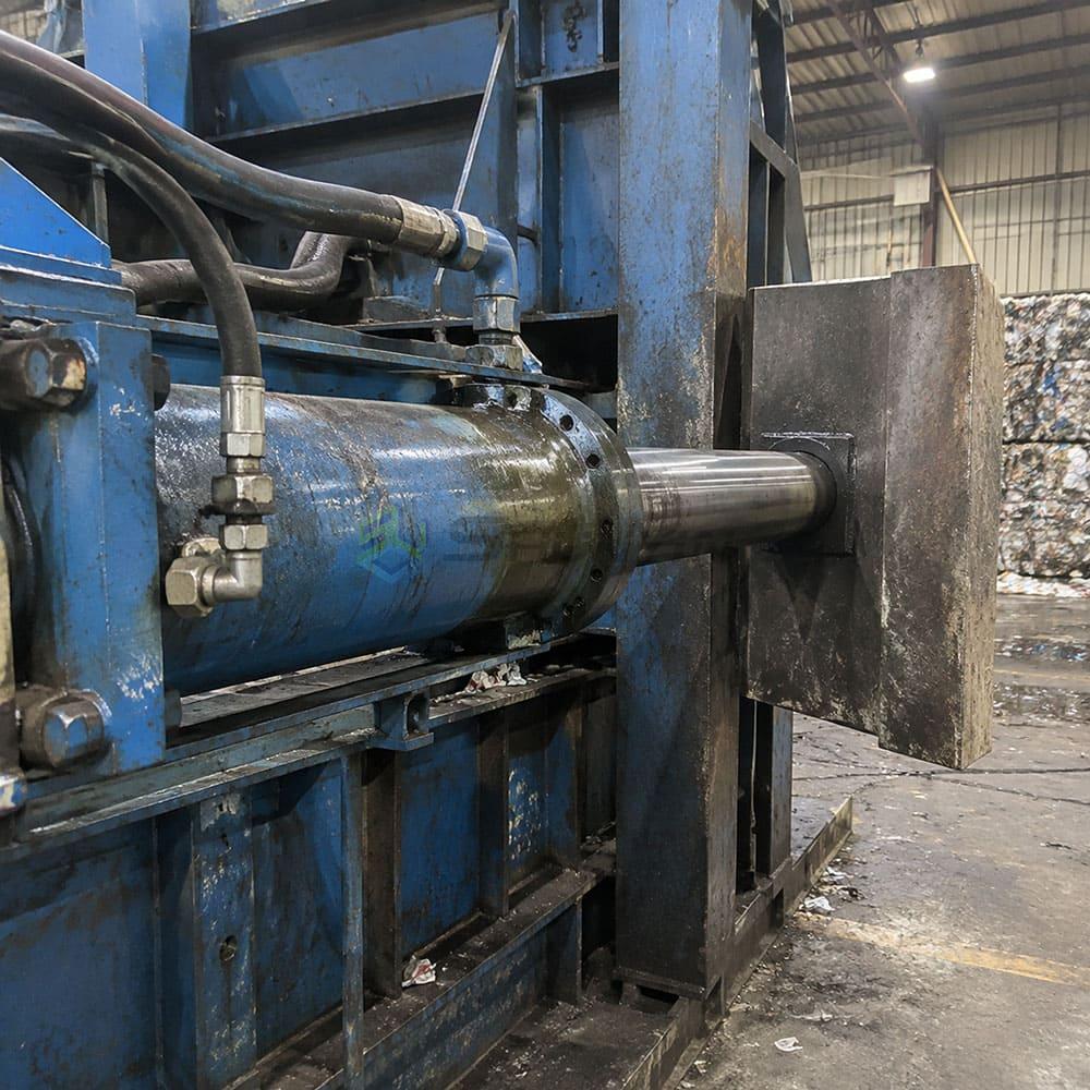
- Main compression cylinder: Drives the horizontal compression platen forward and back
- Pre-press or cross-press cylinders (where fitted): Manage material containment before or during main compression
- Ejection cylinder: Pushes the finished bale out of the chamber
Hydraulic pressure is generated by the pump and regulated through the valve manifold. The system applies that pressure to the cylinder bore, generating the linear force that moves the platen.[^4]
Why Pressure Rating Alone Is Not Sufficient
A few observations from the manufacturing and commissioning side:
Machines with the same cylinder pressure specification can produce significantly different bale densities when operating with the same material, because bale density is affected by chamber volume, stroke length, the number of compression cycles per bale, and how consistently the chamber is loaded.
This is not a flaw — it is physics. A bale is the product of the entire cycle, not just the peak force applied.
Charge Cycles and Bale Build-Up
Most horizontal balers complete multiple compression strokes before a bale is full.[^5] Each stroke is called a charge or charge cycle. The sequence typically works as follows:
- Material is loaded into the feed chamber (manually or automatically)
- The platen advances, compressing the material horizontally into the bale chamber
- The platen retracts, allowing the next load of material to enter
- This charge cycle repeats — often 4 to 10 or more times per bale, depending on material and target bale weight
- When the bale chamber is full (detected by a length sensor, pressure switch, or counter), the machine transitions to the tying stage
The number of charges per bale, and the consistency of each charge, directly affects bale density and weight uniformity. This is where material type, bulk density, and rebound behavior all come back into the equation.
How Are Bales Tied in a Horizontal Baler?
Tying is the stage that determines whether your bale survives handling, transport, and downstream processing. A dense, well-compressed bale that is poorly tied will fall apart before it reaches the weighbridge.
Tying failure is more common than many buyers expect — and it is almost always preventable through correct specification of wire gauge, number of ties, and tying mechanism for the specific material being baled.
Manual vs. Automatic Tying
| Tying Method | Description | Suitable For |
|---|---|---|
| Manual wire tying | Operator threads and secures wire by hand through tie channels | Lower-volume operations, mixed materials |
| Semi-automatic tying | Machine positions wire; operator completes the knot | Mid-volume operations |
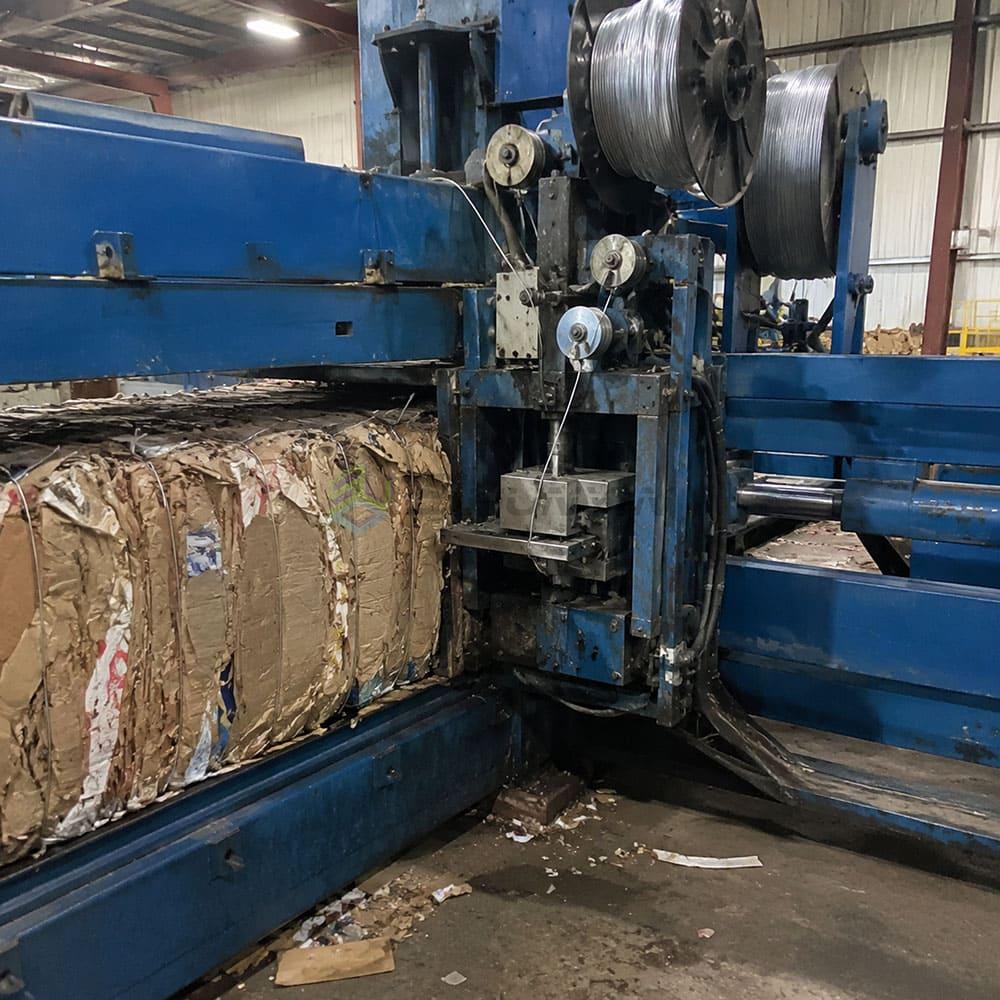
| Fully automatic tying | Machine threads, tensions, and ties wire without operator input | High-volume, continuous operation |
Fully automatic tying substantially increases throughput and reduces labor requirements.[^6] However, the tying mechanism must be correctly specified for the wire gauge and number of ties required by the material.
Wire Gauge, Number of Ties, and Material Behavior
- Cardboard and paper: Typically tied with 3–5 wires, medium gauge. Moderate spring-back means tension must be adequate to prevent loosening.
- Plastic film: High spring-back after compression. Requires adequate wire tension and, in some configurations, more ties to contain the bale.
- Scrap metal: Requires heavier-gauge wire and robust tying mechanisms. Bale weight and density can be high, increasing demands on the tie points.
- PET bottles: Significant rebound when pressure releases. Tie count and wire tension are critical to bale integrity.
From commissioning observations, bale integrity problems almost always trace back to a mismatch between the tying specification and the material's spring-back characteristics — not to a fault in the compression system itself.
How Is the Finished Bale Ejected and Handled?
Bale ejection and downstream handling are often the last things buyers think about and the first things that cause operational bottlenecks after installation.
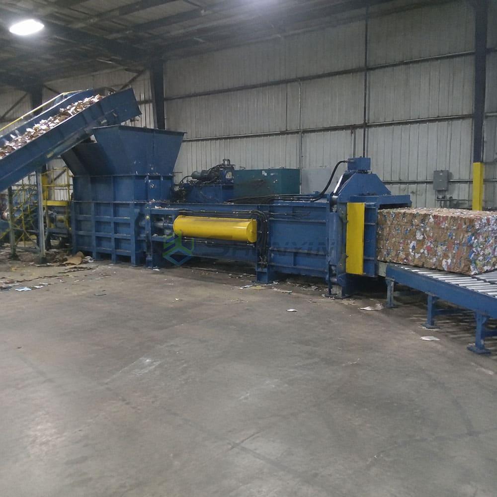
A bale that cannot exit the machine cleanly, or cannot be moved efficiently once ejected, creates a downstream constraint that limits your entire throughput[^7] — even if the compression and tying stages are working perfectly.
The Ejection Mechanism
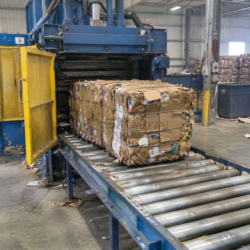
Once tying is complete, the bale is pushed out of the chamber by the ejection cylinder — typically through a side-opening door or through the discharge end of the bale chamber. The direction and mechanism vary by machine design.
Key considerations during machine selection:
- Bale discharge direction relative to your floor layout and downstream conveyor
- Floor-level or elevated discharge for forklift or conveyor integration
- Bale weight and dimensions relative to your handling equipment capacity
Bale Dimensions and Weight
Bale size is determined by the bale chamber geometry, not by how hard you compress.[^8] Chamber width, height, and length set the bale's external dimensions. Compression force and cycle management affect density and weight within that fixed geometry.
Typical horizontal baler bale dimensions and weights vary widely by model and material — buyers should request model-specific documentation and verify claims against the actual material being processed.
Downstream Handling Integration
For high-volume operations, bale ejection should integrate with:
- Roller conveyors or transfer cars for moving bales to storage
- Weighing systems for bale weight recording
- Stacking or strapping stations for export-ready bale preparation
Getting this integration right during the specification stage — rather than after installation — saves significant time and cost.
Frequently Asked Questions
What materials can a horizontal hydraulic baler machine process?
Horizontal balers are widely used for cardboard, OCC, waste paper, plastic film, PET bottles, textiles, and some scrap metal applications. Material type significantly affects machine configuration, including feed design, compression requirements, tying specification, and chamber dimensions. Always verify suitability with the manufacturer for your specific material.
How does a horizontal baler differ from a vertical baler?
A horizontal baler compresses material along a horizontal axis, typically handles higher volumes, and usually produces denser, more uniform bales with less manual labor.[^9] Vertical balers compress downward, are more compact, and are better suited to lower-volume operations. For continuous or high-throughput operations, horizontal configurations are generally more appropriate.
What compression force do I need for my material?
Compression force requirements depend on material type, target bale density, and bale dimensions — not a single universal figure. Cardboard typically requires less force than scrap metal or thick plastics. Consult the manufacturer with your specific material profile and throughput requirements before selecting a model.
How many wire ties does a bale need?
The number of ties depends on material type, bale dimensions, and bale weight. Most horizontal balers apply between 3 and 6 ties per bale. Materials with high spring-back — such as plastic film and PET bottles — typically require more ties and higher wire tension to maintain bale integrity during handling and transport.
Can a horizontal baler be integrated with a conveyor or shredder?
Yes. Horizontal balers are regularly integrated with in-feed conveyors, shredders, and bale-handling conveyors as part of a complete material processing line. Integration requirements — including feed rate, material sizing, and discharge coordination — should be specified during the machine selection process, not added as afterthoughts.
Conclusion
A horizontal hydraulic baler machine works through a coordinated cycle of feeding, compression, tying, and bale ejection — and every stage must be matched to your material, volume, and operational context. Compression force matters, but it is one variable among many. Feed design, charge cycle management, tying specification, and bale-handling integration are equally critical to getting consistent, usable bales.
If you are evaluating a horizontal hydraulic baler for your operation, start with your material profile and throughput requirements — not a datasheet comparison of pressure ratings. Contact our technical team to discuss your specific application and get a configuration recommendation based on what you are actually processing.
[^1]: "Baling Solid Waste to Conserve Sanitary Landfill Space, A ...", https://nepis.epa.gov/Exe/ZyPURL.cgi?Dockey=9100FLI3.TXT. Institutional descriptions of horizontal balers identify feeding, repeated ram compression, bale binding, and discharge as the principal stages of the operating cycle. Evidence role: mechanism; source type: institution. Supports: An institutional technical description should document the principal operating stages of a horizontal baler.. Scope note: Specific sequencing, sensor logic, and ejection arrangements vary among baler designs. [^2]: "Management Tips for Round Bale Hay Harvesting, Moving ...", https://pubs.ext.vt.edu/442/442-454/442-454.html. Compaction research indicates that variations in feed quantity and spatial distribution can produce nonuniform density and less stable processing conditions. Evidence role: mechanism; source type: paper. Supports: Research on compaction or baling should show that feed distribution and charge consistency affect density distribution and process stability.. Scope note: General compaction findings support the mechanism but may not quantify the effect for every horizontal-baler configuration. [^3]: "High-pressure Compaction & Bailing Of Solid Waste", https://nepis.epa.gov/Exe/ZyPURL.cgi?Dockey=2000PVVW.TXT. Experimental studies of baling and compaction report that final density and production rate depend on material characteristics and operating conditions in addition to peak applied force. Evidence role: general_support; source type: paper. Supports: Experimental baling or compaction research should show that density and throughput also depend on material properties, chamber conditions, feed rate, dwell time, and cycle time.. Scope note: Results obtained for a particular waste or biomass material may not provide direct performance values for industrial recyclable-material balers. [^4]: "Pascal's principle - HyperPhysics", http://hyperphysics.phy-astr.gsu.edu/hbase/pasc.html. Hydraulic engineering references define ideal cylinder force as the applied fluid pressure multiplied by the effective piston area, subject to mechanical and hydraulic losses. Evidence role: mechanism; source type: education. Supports: An engineering source should establish that ideal hydraulic-cylinder force equals fluid pressure multiplied by effective piston area.. [^5]: "Design, Analysis and Fabrication of Hydraulic Scrap Baling Machine", https://www.academia.edu/101322561/Design_Analysis_and_Fabrication_of_Hydraulic_Scrap_Baling_Machine. Technical accounts of channel balers describe bale formation as an incremental process in which successive feed charges are compressed by repeated ram strokes. Evidence role: mechanism; source type: institution. Supports: A technical or safety institution should describe repeated feeding and ram cycles used to build a complete bale.. Scope note: The number of strokes required is machine- and material-dependent. [^6]: "[PDF] The Field Baler: Operation and Costs - Open PRAIRIE", https://openprairie.sdstate.edu/cgi/viewcontent.cgi?article=1083&context=agexperimentsta_circ. Research on industrial automation finds that mechanizing repetitive handling and fastening tasks can reduce direct operator time and shorten production cycles. Evidence role: general_support; source type: research. Supports: Independent automation research should show that mechanizing a repetitive manual handling step can reduce labor time and cycle delays.. Scope note: This general automation evidence does not establish a specific throughput gain for every baler, because tying may not be the line's controlling bottleneck. [^7]: "[PDF] Theory of Constraints Case Study in the Make-to-Order Environment", https://upcommons.upc.edu/bitstreams/68316c29-d5a1-44a1-a9d2-7446891a6202/download. Production-systems research establishes that line throughput is constrained by bottleneck stages, including downstream handling operations whose capacity is lower than that of upstream equipment. Evidence role: mechanism; source type: research. Supports: Operations-management research should establish that total line throughput is constrained by the lowest-capacity or most delay-prone stage.. Scope note: This systems principle supports the proposed mechanism but does not show that bale ejection is the bottleneck in any particular installation. [^8]: "[PDF] Validation of Field Test Methods for Use of Tire Bales", https://library.ctr.utexas.edu/ctr-publications/5-5517-01-1.pdf. Baling studies treat chamber geometry as the primary constraint on bale cross-section, while compaction pressure and material response influence density and resulting mass. Evidence role: mechanism; source type: paper. Supports: Baling research should distinguish chamber-defined cross-sectional dimensions from pressure-dependent density and bale mass.. Scope note: Bale length may be adjustable or sensor-controlled, and some materials expand after discharge. [^9]: "[PDF] GENERAL REFERENCE ON RECYCLING EQUIPMENT", https://eec.ky.gov/Environmental-Protection/Waste/recycling-and-local-assistance/recycling/Documents/GeneralReferenceRecyclingEquipment.pdf. Waste-management guidance generally distinguishes vertical balers as compact, batch-operated equipment and horizontal balers as systems more readily configured for continuous or higher-volume processing. Evidence role: general_support; source type: government. Supports: Government or institutional waste-management guidance should distinguish the orientations and typical operating scales of horizontal and vertical balers.. Scope note: Higher density, greater uniformity, and lower labor are not inherent in orientation alone and depend on automation, material, and machine design.